





Timing Belts with Special Machining: Slitting, Grooving, Backings and Custom Modifications
Timing Belts with Special Machining: Slitting, Grooving, Backings and Custom Modifications
How a standard endless belt becomes a machine-specific component: the six machining operations, the backings and the tolerance rules
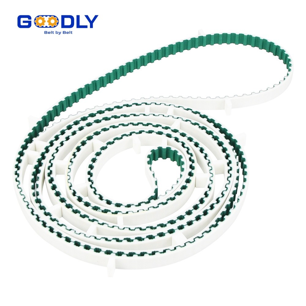
A timing belt with special machining is still a timing belt — same tooth profile, same cord, same pitch length — but its back, edges or body have been cut, punched, ground or covered so it can do something the standard part cannot: carry a product, hold it with vacuum, push it sideways, or stay centred on a long shaft. Machine builders rarely order these features for the drive itself. They order them because one belt is doing two jobs at once, acting as the conveyor, the registration surface or the feeding element as well as the drive. This guide covers the machining operations that make that possible, the backings available, the tracking features that stop a wide belt from walking, and the tolerance limits that decide which modifications are realistic and which will crack in service.
What Is Special Machining on Timing Belts and Why Do Machines Need It?
Special machining covers every operation applied to a cured belt beyond cutting it to width: slitting to a non-standard width, punching vacuum or locating holes, slotting the back, grinding the tooth or back surface, bonding cleats, and adding tracking features. The reason is almost always mechanical — the machine has no room, no vacuum manifold or no separate conveyor, so the belt has to solve the problem itself. The table below maps the usual machine requirement to the machining answer:
| Machine requirement | Standard endless belt | With special machining |
|---|---|---|
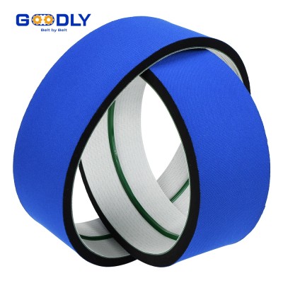
| Belt has to carry or grip the product | Smooth fabric back, no grip | Rubber, foam or friction backing bonded to the back |
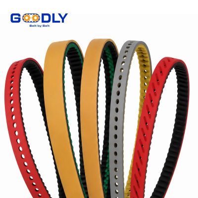
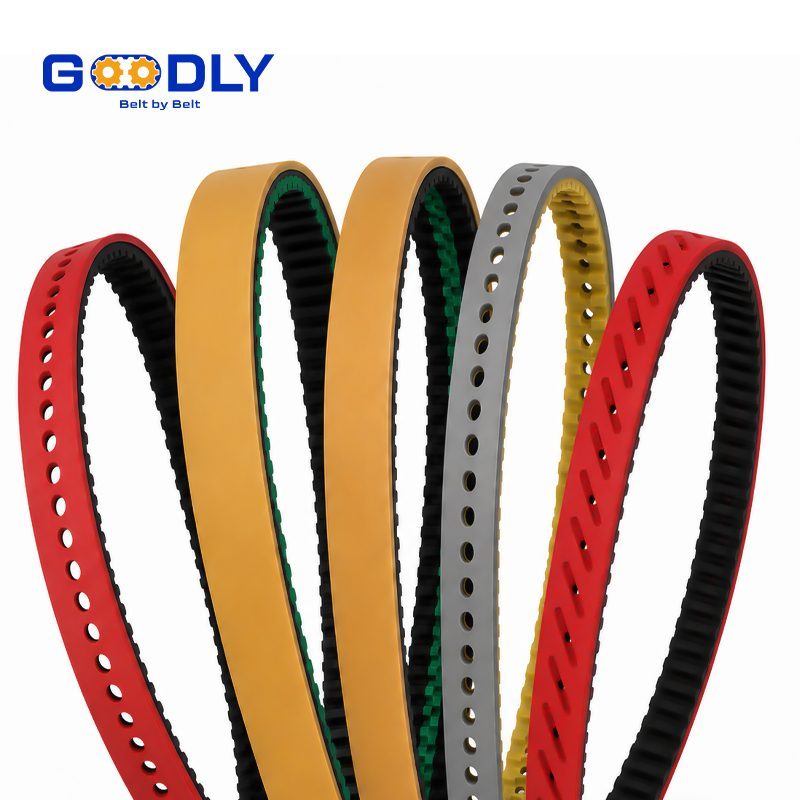
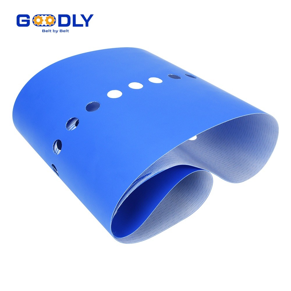
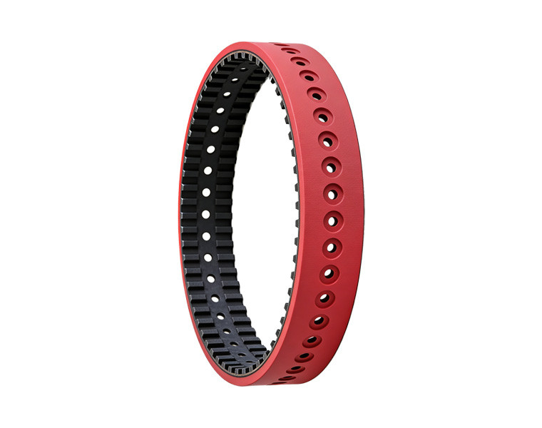
| Product has to be held by vacuum | Solid body, no ports | Punched or slotted holes in rows or zones |
| Belt has to push or index parts | Plain back | Moulded or bonded cleats, lugs and flights |
| Wide belt has to stay on the shaft | Relies on pulley flanges alone | V-guide, centre rib or ground edge |
| Belt has to fit a narrow channel | Stock widths only | Slit to any width inside the sleeve range |
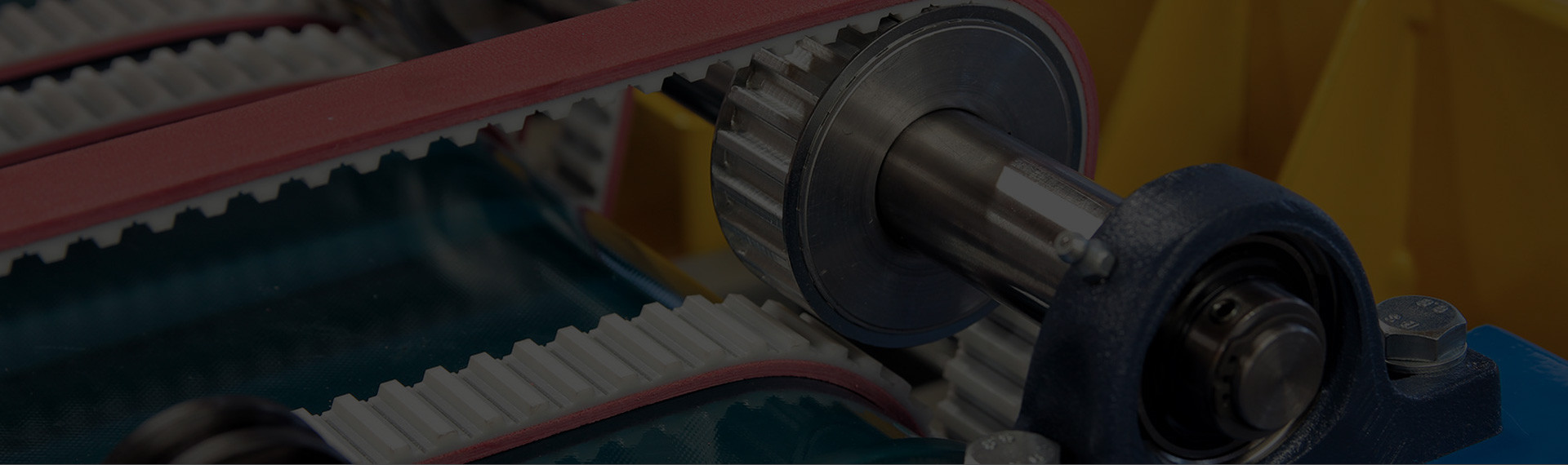
The engineering discipline behind all of it is the same: keep the load path intact. A timing belt carries its load in the cord line, and every modification either stays clear of that line or it trades strength for function. That single rule explains most of the design limits later in this article.
Common Timing Belt Machining Operations: Slitting, Perforating and Grooving
Six operations cover the large majority of industrial requests. Most timing belts with special machining combine two or three of them, and the order matters: cutting and punching happen before coating, grinding happens after curing, and cleats are added last so their position can be referenced to the finished profile.
| Operation | What is done to the belt | Result on the machine | Practical tolerance |
|---|---|---|---|
| Slitting | Cured sleeve cut into narrower belts on multi-blade cutters | Width matched to the channel, no on-site trimming | ±0.2 mm width, square edge |
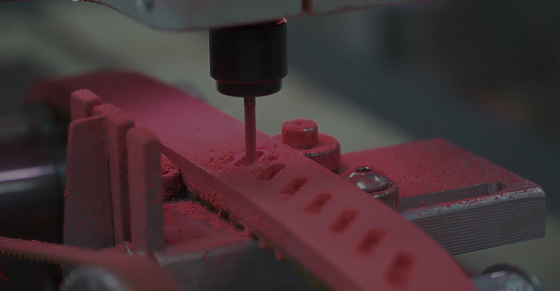
| Perforating and punching | Rows of holes punched or drilled through the body | Vacuum hold-down, air release, locating pins | ±0.3 mm hole position |
| Slotting and grooving | Long slots or grooves cut into the back | Clearance for fingers, rails, sensors and blades | ±0.3 mm slot width |
| Back grinding | Back surface ground to a controlled thickness | Constant height for coating and product contact | ±0.05 mm thickness |
| Cleat bonding and moulding | Cleats, lugs or flights added by vulcanised bonding | Positive pushing, spacing and indexing of parts | ±0.5 mm cleat position |
| Notching and edge profiling | Edges cut with notches, radii or chamfers | Clearance at pulleys, fewer edge cracks | ±0.3 mm |
Adding Timing Belt Backings: Rubber, Foam and Friction Coatings
The backing is what turns a drive belt into a handling belt. It is applied to the back of the belt — the side away from the teeth — and vulcanised or bonded so it becomes part of the body rather than a layer sitting on top of it. Five families cover nearly every application:
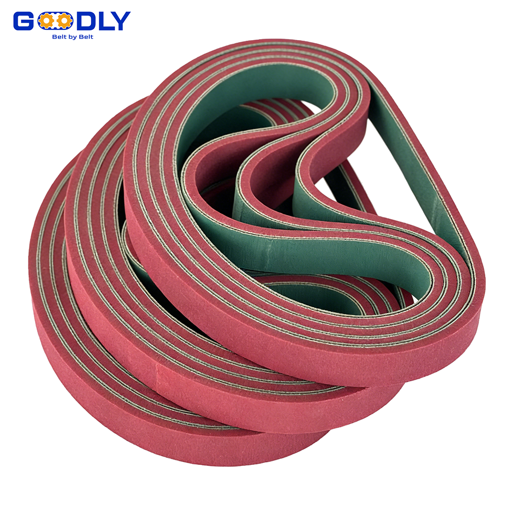
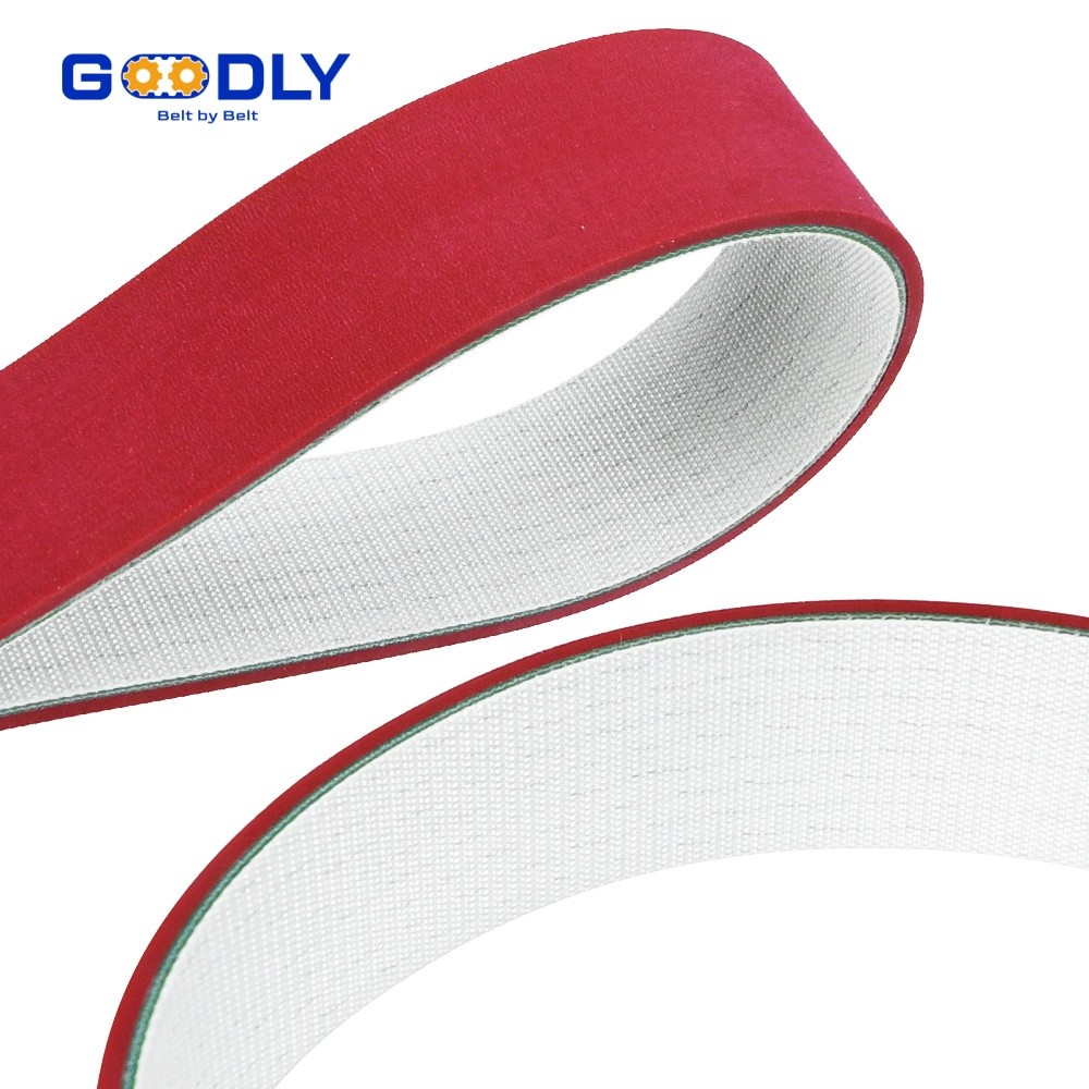
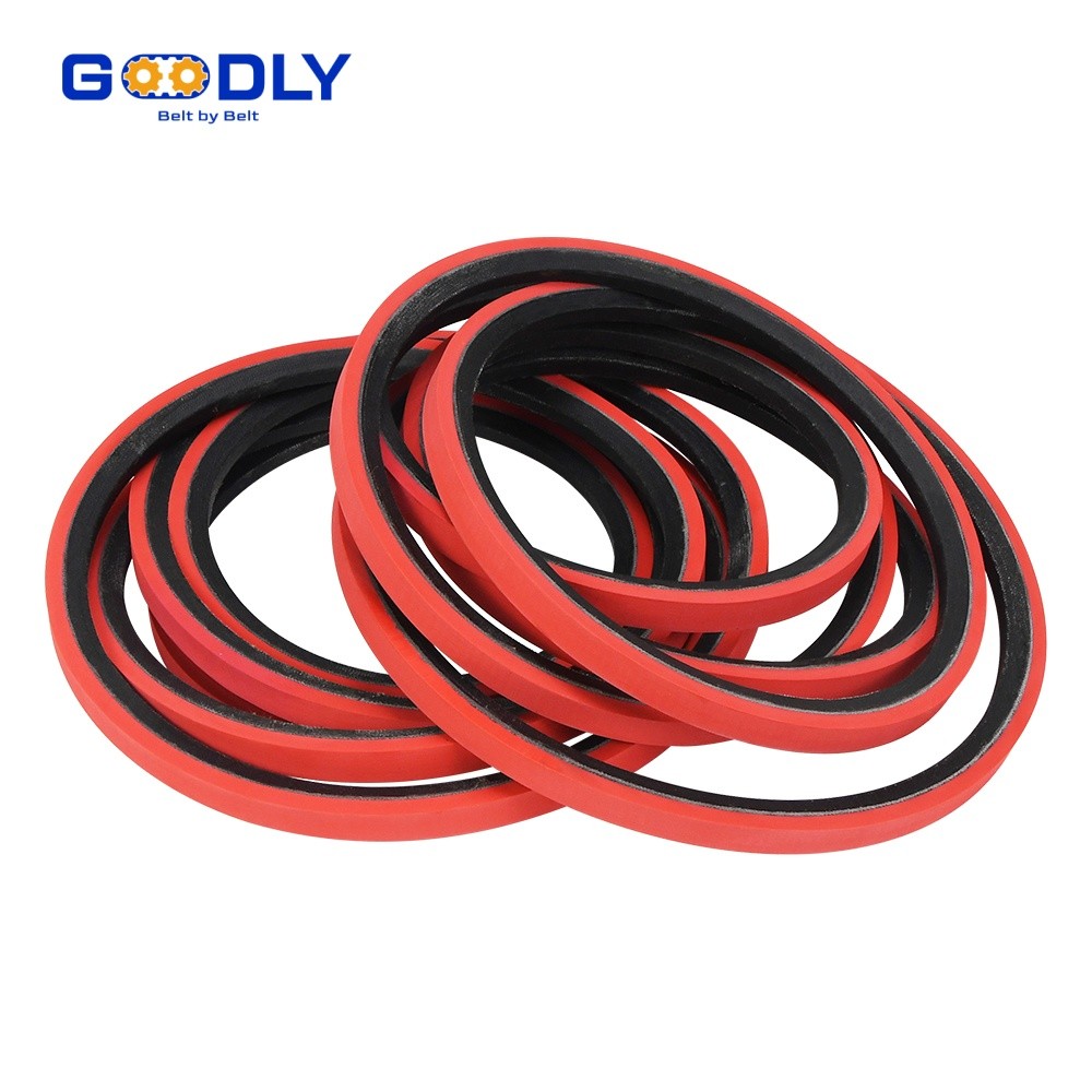
- Rubber backing. The workhorse for grip. A red or black rubber layer gives friction for inclined conveying, sheet feeding and product acceleration, and can be grooved or textured for extra bite. The construction is covered in our rubber coated timing belt guide.
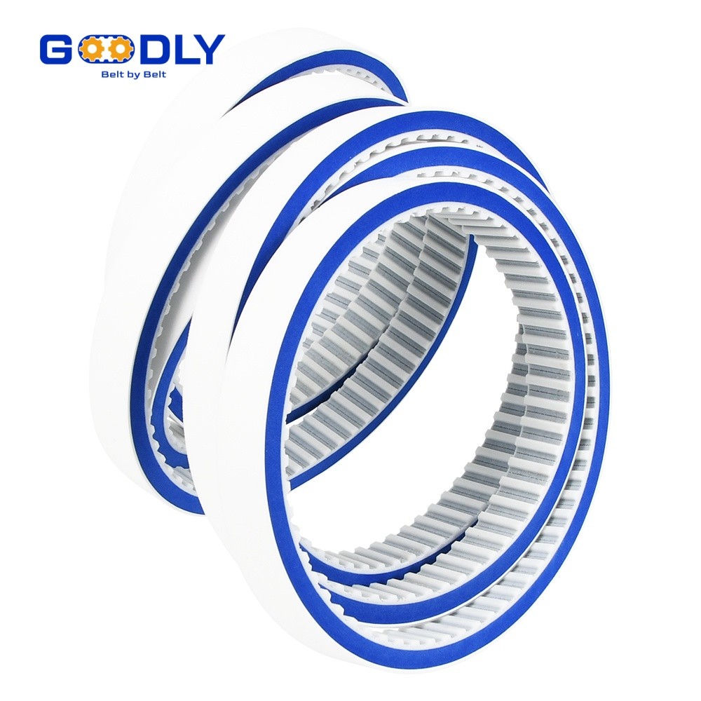
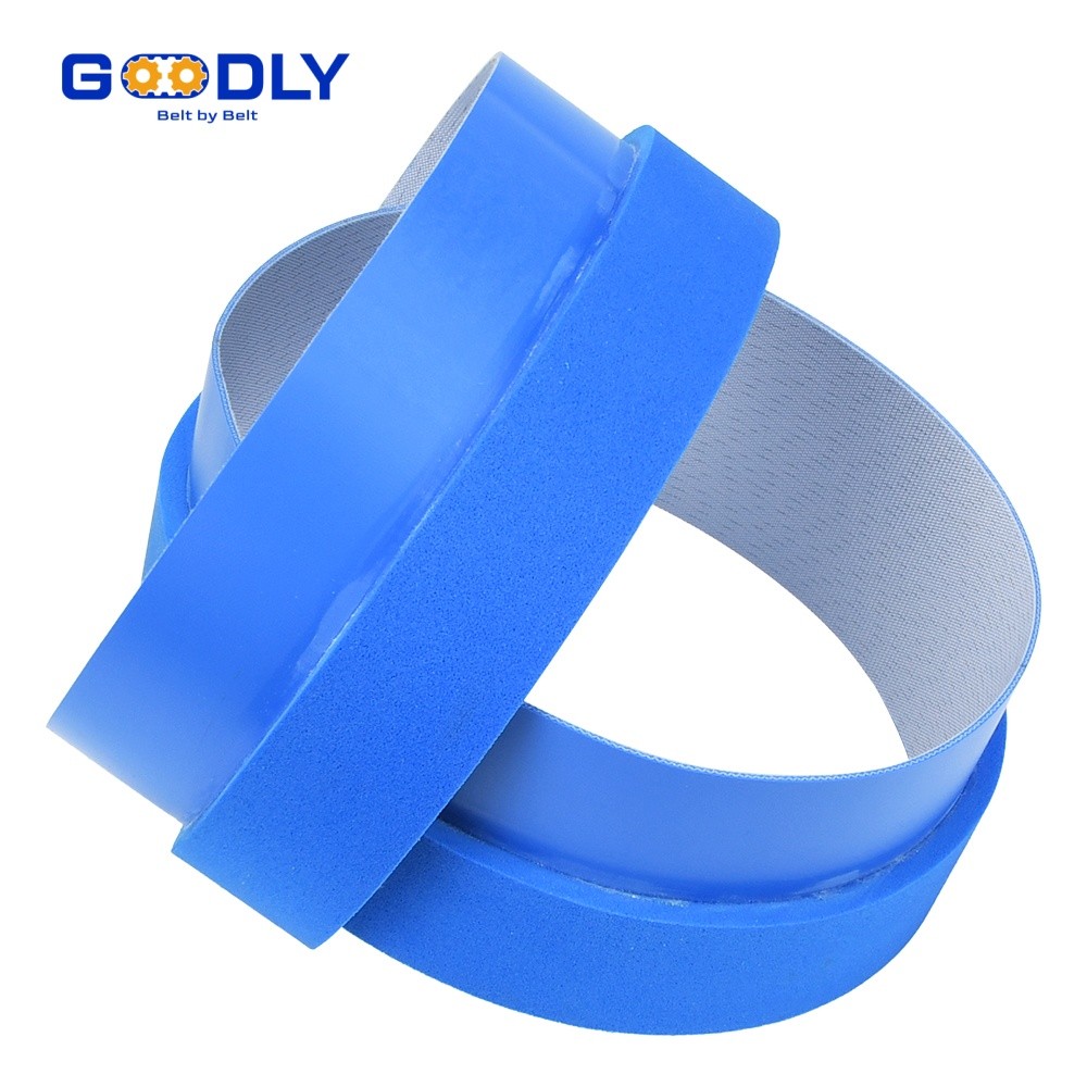
- PU foam and sponge backing. Compressible, gentle and non-marking, used where the product is fragile — glass, electronics, printed cartons, fresh food. Details are on the sponge coated belt page.
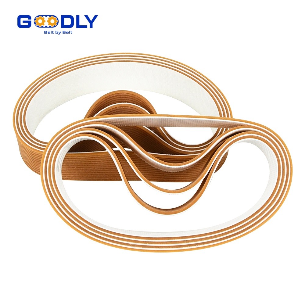
- Fabric backing. Low friction and low noise, used where the belt has to slide against a support rail or where minimal marking matters.
- Friction and grip coatings. Thin, hard-wearing layers applied where a full rubber backing would be too thick for the pulley clearance.
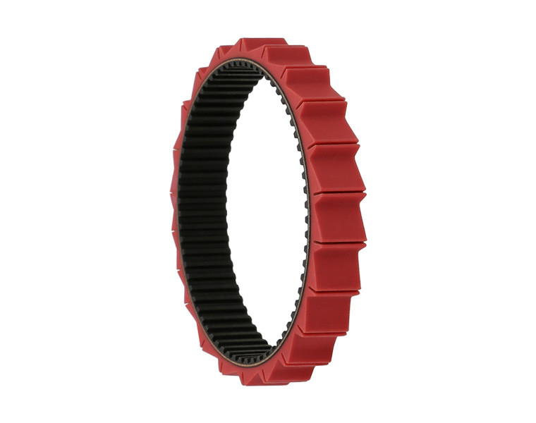
- Cleats and flights. Not a coating but the same family of modification: moulded or bonded profiles that push, space or lift the product. A cleated or coated belt usually replaces a chain-and-flight conveyor entirely.
Timing Belt Tracking Features: V-Guides, Flanges and Profile Modifications
Tracking is the most under-specified feature on wide belts, and the most common cause of a machined belt failing early. A belt 100 mm wide running on a 2 m shaft will walk if nothing stops it, and pulley flanges alone are a poor answer: they rub the belt edge, generate heat and eventually fray the fabric. Four options are used instead:
- V-guide. A triangular rib bonded to the back of the belt runs in a matching groove machined into the pulley. It is the standard solution for wide, slow belts and it corrects misalignment continuously rather than at the edges.
- Centre rib or tracking rib. A rectangular rib, stronger than a V-guide and better at carrying side loads on long spans.
- Ground edge. The slit edge is ground square and true so the belt runs against a fixed rail without fraying. Cheap, effective, and often enough for short centres.
- Profile modification. Crowned or relieved tooth flanks and matched pulley crowning, used where the belt has to self-centre at speed. Tooth geometry options are mapped in our tooth profiles and pitches guide.
How Machining Affects Belt Strength, Balance and Service Life
A machined belt is a modified structure, and the modification becomes the new weak point. Four effects matter in practice:
- Holes reduce the cord cross-section. A row of large holes punched through the body removes material above the cord line. Keep the row one full pitch away from the edge and never cut into the cord itself; a cut cord is a broken load path that fails without warning.
- The cleat bond is a fatigue point. Every pulley the belt wraps flexes the cleat root. Tall cleats on small pulleys crack first, which is why cleat height is limited by the smallest pulley in the drive, not by the product.
- Back grinding thins the body. Removing material to hold a flat contact surface is fine up to a limit; past it the tooth body flexes more and runs hotter.
- Balance changes at speed. Asymmetric machining — holes on one side, cleats on the other — matters on high-speed drives and not at all on a 20 m/min conveyor. State the belt speed when you specify the feature.
None of these are reasons to avoid machining. They are the reasons to specify it with the belt's duty in writing, so the machinist knows what the feature has to survive.
Design Rules for Machined Timing Belts: Tolerances and Material Limits
The rules below are the practical limits we work to when reviewing a drawing for timing belts with special machining. They hold across rubber and PU constructions, with silicone needing slightly more clearance because its tear strength is lower:
| Design point | Practical rule | Why it matters |
|---|---|---|
| Hole row to belt edge | Keep at least one full tooth pitch of solid body | Edge tears start where the cord is exposed |
| Hole diameter vs cord line | Stop the punch above the cord, never through it | A cut cord fails instantly under load |
| Cleat height vs pulley | Cleat must clear the smallest pulley in the drive | Tall cleats crack at the root on tight wraps |
| Backing thickness | Stay under about 3 mm on standard profiles | Thick backing stiffens the belt and overloads the teeth |
| Minimum width after slitting | Keep above 6-8 mm | Very narrow belts lose tracking stability |
| Groove depth | Less than half the backing thickness | Deep grooves become crack initiators |
| Coating hardness | Choose by grip requirement, not by habit | Soft coatings grip more but wear faster |
GOODLY Special Machining Capabilities: Send Your Drawings for Review
GOODLY runs slitting, punching, slotting, back grinding, cleat bonding and edge profiling in the same plant that moulds and cures the belts, which is what makes short runs of highly modified belts practical. Reviewed drawings usually come back with two answers — what you asked for, and the version that will survive the pulley. The working sequence is short:
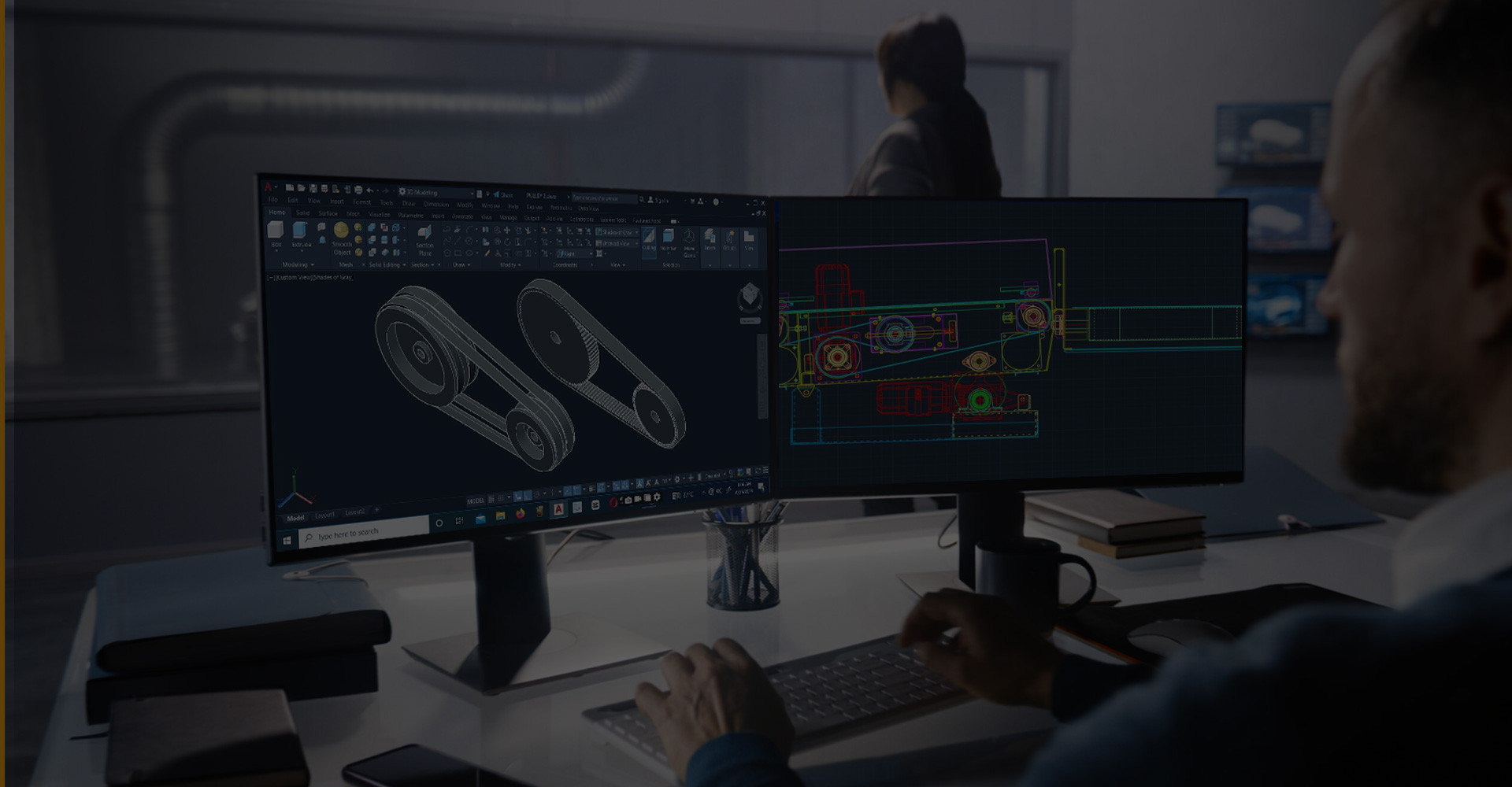
1. Send the drawing or the sample. A CAD file, a sketch with dimensions, or a worn belt with the feature marked is enough to start. Include belt code, pitch, width and the smallest pulley.
2. Engineering review within 24 hours. We check cord clearance, cleat height against pulley diameter, backing thickness and tracking method, and flag anything that will fail early.
3. Prototype in 3-5 working days. Machined and inspected in-house, with the feature positions measured and recorded against your drawing.
4. Approve, then repeat identically. Approved constructions are held with retained samples so the second order matches the first, feature for feature.
The full capability list sits on the Timing Belts with Special Machining page, and the coating side is described on the custom rubber coated belt page. For construction choices — endless, open-ended or spliced — start with our construction types guide, and for length, profile and colour options see the custom timing belt checklist.
What is the difference between a cleated belt and a rubber coated belt?
A rubber coated belt has a continuous friction layer bonded to its back, so it grips the product across the full width. A cleated belt has discrete profiles — cleats, lugs or flights — bonded or moulded on at intervals, so it pushes or spaces the product instead of gripping it. Many handling belts use both: a rubber backing for grip plus a cleat every few hundred millimetres to stop the product sliding back on an incline.
Can any timing belt be punched or perforated?
Almost any cured rubber or PU belt can be punched, but the pattern has to respect the cord line. Holes that stop above the cord are routine; holes through the cord are not, because they cut the load path and the belt fails at the hole. For vacuum conveying, keep hole rows inside the width, space them evenly and expect the punch pattern to be tied to the tooth pitch so the belt indexes predictably.
How much width tolerance can slitting hold?
Plus or minus 0.2 mm on width with a square edge is normal for a cured sleeve cut on a multi-blade cutter. If your channel needs tighter, tell us the fit and we will grind the edge instead of only slitting it — the cost difference is small, the tracking difference is not.
Does special machining weaken the belt?
It changes where the belt is weakest. A well-designed modification on a timing belt with special machining leaves the cord and the tooth root untouched, and the belt then performs like the standard part. A badly designed one puts a hole, groove or cleat root where the stress already concentrates, and that becomes the failure point. This is exactly what the drawing review is for.
Can you machine belts I already buy elsewhere?
We quote machining on our own constructions, because the backing bond and the cleat bond have to be cured into a belt we made and inspected. Send the specification of the belt you are running and we will match the construction first, then add the machining — which also removes the mismatch risk between two suppliers.
Send Your Belt Drawing for a Machining Review
GOODLY reviews drawings for timing belts with special machining against the real cord line and pulley geometry before quoting, samples prototypes in 3-5 working days, and repeats approved constructions identically. Send the drawing, the belt code or a photo of the feature you need — our engineers will come back with a feasible specification, not a catalogue number.
Submit a Drawing for Review